
Troubleshooting 8381
3.0 GENERAL
This Chapter describes procedures for troubleshooting an installed CodeNet transceiver. You can usually ascertain whether or not your unit is functioning correctly by observing the activity of the diagnostic/activity LEDs located on the front panel, as shown in Figure 3-1.
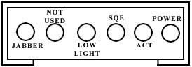
FIGURE 3-1. The front panel of Fiber Optic Ethernet Transceiver
3.1 INDICATORS
POWER (GREEN) - On when the CodeNet is properly connected via AUI cable to an active Ethernet interface.
SQE: COLLISION PRESENCE (YELLOW) - This LED illuminates when a card is receiving a packet at the same time it is transmitting a packet. Occasional collisions are normal in an Ethernet network. This does not denote an error condition.
ACT: ACTIVITY (GREEN) - This LED illuminates when the card is receiving or sending a packet. This indicates normal operation.
LOW LIGHT LEVEL (YELLOW) - This LED illuminates if the received power is less than the receiver sensitivity.
JABBER (YELLOW) - This LED illuminates when a transceiver interlock circuit is activated. This circuit prevents a runaway AUI controller from saturating the network. On when DTE packet is too long, off when traffic is normal.
HIGH LIGHT (YELLOW) - This LED illuminates if the received power is greater than the receiver saturation level.
3.2 ERROR CONDITIONS
The front panel lights on the 8381 indicate the folk}wing conditions. If any of these indicators illuminate, follow the error correction steps given in Section 3.3.
3.3 PROBABLE CAUSES OF TROUBLE
NOT THAT THE TERM "COMPANION UNIT(S)" IS USED EXTENSIVELY THROUGHOUT THIS SECTION. THIS TERM REFERS TO CODENET-3311s, CODENET-3310s AND/OR CODENET-8311s CONNECTED TO THE 8381. THE TERM IS USED TO AVOID REDUNDANCY.
3.3.1 If the CodeNet-8381's POWER LED does not light it means that the unit is not receiving power from the DTE. In this case, the problem may be one of the following:
(1) NO power from DTE. Ethernet DTE units with a BNC or Twisted Pair interface and a 15-pin AUI connection have a switch setting to determine which interface is active. This must be set in the AUI position to power the unit. Check this setting.
(2) Improper Ethernet pigtail transceiver cable connection.
(3) Defective DTE.
(4) Defective extension cable.
(5) Defective 8381 transceiver.
Troubleshooting - green POWER LED does not illuminate. Before going any further, ensure that the unit is correctly installed by reviewing the installation instructions. Check to see that your transceiver cable is installed and securely fastened.
If the green front panel POWER LED still does not illuminate you must:
If these steps have been taken, the unit's front panel's green POWER LED should illuminate. If possible, use a known good 8381 to isolate a potentially defective 8381.
If a known good 8381's green POWER light still does not illuminate, check the AUI card by swapping with a known good AUI card. If the problem is not alleviated swap the DTE itself.
3.3.2 If the green POWER LED is ON (unit receiving power), the optical fibers are connected to both the 8381 and a CodeStar passive hub, and the yellow LOW LIGHT LED illuminates, this means that the 8381 receiver is not receiving its own Ethernet packet from the passive star. The problem may be one of the following:
Excessive optical loss may be due to one or more of the following:
Troubleshooting - YELLOW LOW LIGHT LED on.
If the unit's yellow LOW LIGHT LED illuminates you must:
(1) Network break somewhere else in network.
(2) Heartbeat switch is ON in the 8381 and the unit is attached to a repeater.
(3) 8381's transmitter is defective.
(4) Companion unit's receiver is defective.
(5) Network software (or monitor) is not properly installed.
Troubleshooting - Normal LED indication (green POWER LED on, yellow LOW LIGHT LED off) but will not connect to server. In this event you should:
If server connects to a known good DTE, then the problem is the DTE link. In this case, follow these action items until the problem is found.
Ensure that known good 8381 switches arc in factory settings.
If these steps do not solve the problem, recheck the software installation.
3.4 POWER OUTPUT TEST
CAUTION: DO NOT ATTEMPT TO PERFORM THE FOLLOWING POWER OUTPUT TESTS WITHOUT FULL KNOWLEDGE OF RELEVANT OPTION SWITCHES TO BE USED IN THIS TEST. PLEASE FAMILIARIZE YOURSELF WITH PROPER SWITCH SETTINGS.
To perform this test you will need an optical power meter (Codcnoll CTC-2000 or equivalent) connectorized optical section fiber cable.
(1) Power up the unit. The green "POWER" LED should illuminate.
NOTE: That if the receive (RX) port isn't connected to an active companion unit, the yellow Low Light LED will illuminate. This is normal.
(2) Locate the TX (Out) fiber optic port on the 8381. This is the port you will be connecting to one end of the jumper cable. Then connect the other end to the power meter.
(3) If RX is connected, remove the fiber for this test.
(4) Measure the AVG (average) power output on the Codenoll CTC-2000 optical power meter. Your reading will be one-half of the Peak Power.
(5) Verify that the power reading is within acceptable limits as set tbrth in Specifications. Record findings. Note that the size of your jumper cable will determine the launch power.
(6) Remove the optical power meter from the fiber optic pigtail and reattach fiber connectors in both units.
(7) When testing any fiber optic unit always follow these procedures as stated above.
3.5 THE HEARTBEAT FUNCTION
The 8381 is designed to operate with IEEE-802.3 electronic repeaters which will not operate with Heartbeat enabled. In rare cases, however, the AUI controller in the DTE requires Heartbeat and will not function properly without it. Check the AUI controller's manual to see if Heartbeat is required. If it is, enable Heartbeat by turning it on via the 8-position DlP switch.
3.6 OTHER ERROR CORRECTION STEPS
If the CodeNet transceivers do not operate properly, follow the steps listed here to verify correct installation,
(1) Verify that the network connectors are securely attached (TX to IN, RX to OUT on a passive star).
(2) Check the cable connections to other computers and devices.
(3) Ensure that the interconnecting cables used meet Codenell standards.
(4) Allow five minutes of warm-up time in extreme cold conditions to allow for temperature stabilization inside the compuler.
Passive Ethernet
Active Ethernet
Hubs
Switches
Request For Quote
New Products
Downloads
Manuals
Troubleshooting
E-mail Tech Support